Graphite Heating Element Design Guide for Vacuum Furnaces
May 20, 2026
Introduction
In my work at SHJ CARBON, I often discuss the same practical question with customer engineers: "Most graphite heater concepts can be made-but how do we make the temperature field, lifetime, maintenance risk, and cost truly controllable?"
Furnace types and process windows vary significantly, so I try not to force a one-sentence conclusion onto every case. A more reliable approach is to clarify the physical principles, key parameters, and structural methods so you can judge fit against your boundary conditions. When needed, we can also fill in missing constraints together and identify risk points early.

Terminology note: temperature field means the temperature distribution inside the chamber (uniformity, gradients, hot spots). Hot zone refers to the hot-zone assembly/system (heating elements, insulation, supports, electrical joints, electrodes, and gas paths).
- Engineering workflow: principles → objectives & constraints → material selection → electro-thermal sizing & structure → thermal stress & joints → simulation & iteration
- Core formulas: Q = I2Rt, R = ρL/A, P = U2/R, σ ∝ E·α·ΔT
- High-impact tactics: cold-end compensation, power-density control, transition fillet radius (R), zoned heating control
- Engineer-ready tools: symbolic derivation template (U → P → R → L/A), FMEA quick table, and a 10-point review checklist
1) Why Graphite Heaters Generate Stable Heat (Joule Heating Effect)
Most industrial furnace heaters rely on the Joule heating effect: when current passes through a conductor, electrical energy is irreversibly converted into heat due to resistance:
Q = I2 × R × t
- Q: heat (J)
- I: current (A)
- R: resistance (Ω)
- t: time (s)

In design reviews, I always highlight the I2 term: heating is not linear with current. If current density concentrates locally, temperature rise can become very sharp. Many sudden hot-spot issues are triggered by current-path changes, cross-section discontinuities, or contact-resistance drift.
Graphite grade differences (porosity, crystallinity, impurity system) affect resistivity, thermal conductivity, thermal expansion, and volatilisation/contamination risk-which directly impacts the temperature field and lifetime reliability.
2) Quantify Objectives & Constraints First (Engineering Input Checklist)
Before selecting a graphite grade or drawing geometry, I align the inputs with customers as quantitatively as possible:
- Temperature targets: max/normal temperature, soak time, ramp curve
- Uniformity spec: allowed ΔT (centre-edge, top-bottom, loaded vs empty)
- Power & heating rate: required power, ramp rate, control strategy (zoned or not)
- Atmosphere & cleanliness: vacuum level, inert gas type/purity, oxygen/moisture risk, volatilisation limits
- Lifetime & reliability: expected lifetime, allowable resistance growth, maintenance window and accessibility
- Geometric & installation constraints: hot-zone envelope, electrode type, installation method, service clearance
This step can look "non-technical", but it determines the route. Many late-stage changes happen simply because constraints were not defined early enough.
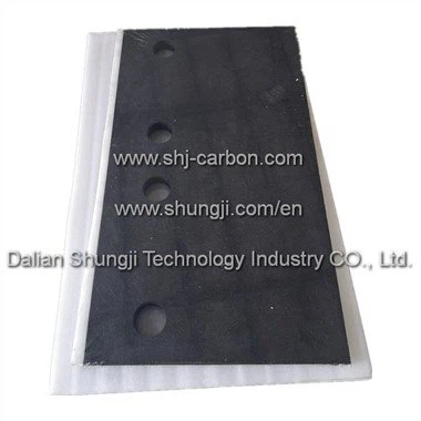
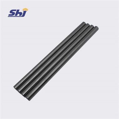
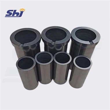
3) Isostatic vs Molded Graphite: Grade Trade-Offs That Drive Performance
A common mistake is to ask only "Do you have graphite?" and not "Which graphite system/grade?" Raw materials and manufacturing routes can change properties significantly.
| Property | High-performance (Isostatic) | Economical (Molded/Formed) | Real design impact |
|---|---|---|---|
| Thermal conductivity | Higher | Lower | Better uniformity, but stronger end heat loss (cold-end effect) |
| Electrical resistivity | Lower, more isotropic | Higher, may be directional | Directionality can reshape temperature distribution |
| Strength / thermal shock | Higher | Lower | Thermal stress is a common failure driver |
| Purity / ash | Higher purity | Average | Impurity volatilisation can contaminate vacuum processes |
| Complex features | Controlled | Often easier | Threads/grooves/fillets feasibility differs |

Dense, high-purity graphite often has higher thermal conductivity and lower resistivity, creating a trade-off between uniformity and power matching.
Related: Isostatic Graphite
4) Resistance Sizing: R = ρL/A & Power Matching (P = U²/R)
This is where objectives turn into drawings. The core sizing equations are:
R = ρ × L / A
P = U2 / R
For a given supply voltage U, you tune L and A to reach target resistance R, and therefore target power P. I also verify whether joints may introduce non-negligible contact resistance.
4.1 Symbolic Derivation Template (U → P → R → L/A)
- Step 0: choose Tdesign and use ρ(Tdesign).
- Step 1: Rtotal = U2 / Ptarget
- Step 2: Itotal = U / Rtotal = Ptarget / U
- Step 3: convert to Runit based on series/parallel/zoned topology.
- Step 4: L/A = Runit / ρ(Tdesign) (or segmented: R ≈ ρ·Σ(Lj/Aj)).
- Step 5: choose manufacturable A, then L = (Runit·A) / ρ(Tdesign).
- Step 6: check current density and power density to prevent local overheating.

4.2 What Happens When Heater Power Density Is Too High?
- Local overheating → larger ΔT → higher thermal stress
- Accelerated ageing → faster resistance growth → harder control stability
- Temperature patches → worse process consistency
5) Cold-End Effect Compensation (End Drop & Early Signs of Cracking)
5.1 What Is the Cold-End Effect?
Conductive electrodes (especially water-cooled designs) act as a heat sink. As a result, heater ends tend to run cooler and the temperature field collapses at both ends. Without compensation, temperature uniformity targets become difficult to achieve.

5.2 Three Early Signals of End Cracking
- Under the same power, end temperature drop becomes progressively more obvious.
- Fine cracks or chipping appear in end/transition zones.
- Abnormal heating near joints (contact resistance rises, local temperature spikes).
5.3 Typical Compensation Structures
- Thicker ends: lower end resistance, smoother overall temperature distribution
- Non-heating conductive end sections: define ends as connection zones to reduce gradients
- Dog-bone variable cross-section: thin middle, thick ends to offset end heat loss

5.4 Why Transition Fillet Radius (R) Is Lifetime-Critical
Sharp corners and abrupt transitions often create stress concentration and current crowding at the same location. A robust fillet radius helps reduce cracking risk, improves uniformity, and lowers chipping risk during machining.

6) Why Graphite Heaters Crack (Thermal Stress σ ∝ E·α·ΔT + Joint Strategy)
Graphite is brittle compared with metals, so lifetime issues are often driven by thermal stress and stress concentration, not room-temperature strength. A practical relationship is:
σ ∝ E × α × ΔT
- E: elastic modulus
- α: thermal expansion coefficient
- ΔT: internal temperature difference
6.1 Three Steps to Reduce Thermal-Stress Risk
- Reduce ΔT first: improve uniformity via conductivity, power density, and cold-end compensation.
- Optimise material parameters: prefer lower α and appropriate E (fine-grain systems may help).
- Eliminate weak points: use fillets, avoid sharp corners, reduce section jumps, avoid notches.
6.2 Joints and Electrodes: Where Many Real Failures Start
Electrodes (Cu/Mo etc.) and graphite expand differently. Rigid joints can fail during thermal cycling. A robust approach is often taper fit + spring preload to allow compliance and reduce stress transfer.
7) FMEA Quick Table (Failure Mode → Cause → Countermeasure)
This table helps engineers quickly decide what to check next. It does not replace detailed simulation or failure analysis, but it is effective for first-pass diagnosis.

| Failure mode | Typical symptoms/impact | Likely causes | Countermeasures |
|---|---|---|---|
| Cold-end / transition cracking | End chipping, cracks grow; end drop worsens temperature uniformity | Large ΔT from end loss; insufficient fillet R; section jump; power density too high | Thicker ends / non-heating end section / dog-bone; increase fillet R; reduce power density; zoned control |
| Abnormal heating at joints (high contact resistance) | Local overheating; resistance drift; arc risk | Poor contact flatness/contamination; insufficient preload; mismatched expansion; small interface area | Increase interface area; control surface/fit; taper fit + spring preload; preload/torque standard |
| Local hot spots / temperature patches | Hot zones, ageing, cracking; process inconsistency | Current crowding at section changes/grooves; anisotropy; asymmetrical insulation/radiation | Smooth transitions; fillets at groove ends; optimise current path; zoned control; electro-thermal simulation |
| Chipping/notches initiating cracks | Cracks start at defects; lifetime drops after handling/assembly | Machining chipping; sharp edges; holes/slots too close to edges; transport impact | Edge chamfer/fillet; adjust minimum edge distance; deburr control; packaging & handling protection |
| Oxidation/erosion (atmosphere issue) | Powdering, dimension loss, strength drop; sudden lifetime loss | O2/H2O ingress; poor purge; high dew point; frequent door opening | Leak control & purge protocol; dew point control; shielding/coating; optimise gas path |
8) Simulation Workflow (Electro-Thermal & Thermal-Stress Coupling)
I treat simulation as a tool to reduce trial-and-error cost. Two coupling workflows are especially useful for graphite heater design in a vacuum furnace hot zone:
- Electro-thermal coupling simulation: calculates current density and heat distribution; hot spots are frequently not where intuition expects.
- Thermo-mechanical (thermal-stress) coupling simulation: uses temperature-field results to compute stress distribution, locate maximum-stress points, and estimate safety margin.
- Iteration: adjust shape (end compensation, variable section, fillets), size (section/length/path), and strategy (zoned power, series/parallel topology) until targets are met.

9) 10-Point Design Review Checklist (Engineer-Ready)
- Temperature targets (max/normal/soak)
- Uniformity target (centre-edge, top-bottom)
- Atmosphere & purity (vacuum level, gas type, oxygen/moisture risk)
- Power and heating rate
- Supply constraints (U/I range, zoned control capability)
- Selection priority order (uniformity / ramp / cleanliness / lifetime / cost)
- Resistance sizing: R = ρL/A; power matching: P = U²/R
- Power density and hot-spot risk
- Structural risk controls: cold-end compensation, fillet R, variable section, zoned strategy
- Connection strategy: electrode matching, taper fit/spring preload, service accessibility
10) What We Need to Provide a First-Round Recommendation (Friendly CTA)
If you would like a quick selection & design direction for your graphite heating element in a vacuum furnace hot zone, these inputs are usually enough:
- Target temperature (max/normal) + ramp/soak curve
- Chamber/hot-zone size (effective hot zone) + loading method
- Atmosphere type (vacuum range / inert gas type & purity / oxygen-leak risk)
- Temperature uniformity requirement (ΔT spec)
- Power supply conditions (voltage/current, zoned control or not)
- Priority order: uniformity / ramp speed / cleanliness / lifetime / cost
Typically, we can start with grade direction + structural risk points + resistance/power matching logic, then decide whether simulation or sample validation is warranted.
Useful references: Graphite Heating Elements | Isostatic Graphite | Contact Us
Closing Note
Graphite heating element design is essentially about balancing real trade-offs: uniformity vs heating rate, thermal conductivity vs resistivity matching, strength vs complexity, and performance vs cost.
For typical operating windows, many issues can be controlled early through quantified objectives, correct resistance sizing, cold-end compensation, and joint strategy. For extreme windows, simulation helps locate hot spots and high-stress points first-then you iterate with confidence.