Why Does a Vacuum Furnace Take Longer to Pump Down After Graphite Felt Replacement?
Nov 06, 2026
Introduction
In our previous article, How Do I Know If Your Vacuum Furnace Insulation Needs Replacement?, we looked at the signs that graphite felt and other insulation materials may need attention. Over time, slower heating, increasing power consumption, visible deterioration, and fiber dusting can all indicate that the insulation system needs closer inspection.
Replacing worn insulation is an important part of furnace maintenance. However, the work does not always end once the new material has been installed and the furnace is reassembled.
After the furnace is returned to service, operators may notice that it takes longer to reach the required vacuum level than it did before maintenance. The pump-down curve may develop a longer tail, or the pressure may stop falling at the expected rate.
When this happens, it is natural to question the replacement graphite felt. Could it be retaining too much moisture? Is the material releasing more gas than expected? Or has something changed in the hot-zone assembly during installation?
These are reasonable questions, but the material itself should not be the first thing blamed. A slow vacuum furnace pump-down can result from several factors, including changes to the vacuum system, moisture and contamination, or differences in the way the insulation layers have been assembled.
The most useful approach is to compare the operating records first, then work through the possible causes in a logical order. This helps distinguish a material-related issue from a problem elsewhere in the furnace and avoids unnecessary replacement work.
1. Start by Understanding the Change in Pump-Down Performance
Before investigating the insulation, it is worth establishing exactly how the pump-down performance has changed. A longer evacuation time is an observation, but it does not explain what caused the difference.
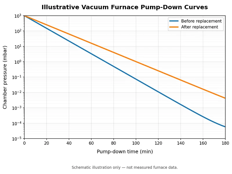
The pump-down curve provides a useful starting point because it shows how chamber pressure changes over time. Comparing the curves recorded before and after graphite felt replacement can help identify when the difference first appears.
Compare the Conditions Before and After Replacement
For the comparison to be meaningful, the two tests should be carried out under reasonably similar conditions.
Consider whether the furnace was tested with the same pump configuration, valve sequence, loading condition, and initial pressure. The position and condition of the vacuum gauge should also be taken into account. Even differences in how long the furnace remained open during maintenance can influence the initial gas load.
These details are particularly relevant when a furnace is tested immediately after insulation replacement. During maintenance, the hot zone is exposed to the surrounding atmosphere, and its surfaces may adsorb moisture or other gases before the furnace is closed again.
Once the operating conditions have been compared, look more closely at the shape of the pressure-time curve.
If the difference appears early in the pump-down process, the pumping system, valves, connections, and possible leaks deserve attention. If the initial stage remains similar but the pressure falls more slowly at lower pressures, gas release from internal surfaces, insulation, or enclosed spaces may be contributing to the problem.
Neither pattern identifies a single cause on its own. However, understanding where the curves begin to diverge gives the maintenance team a more useful direction for further investigation.
If the curves separate early, review the pumping system, valves, connections and possible leaks first. If the difference becomes more noticeable at lower pressures, consider moisture, contamination and gas release from internal surfaces or insulation. These patterns guide the investigation; they do not prove a single cause.
2. Could the Maintenance Work Have Affected the Vacuum System?
Replacing graphite felt often involves opening the furnace and removing or repositioning parts of the hot-zone assembly. Depending on the furnace design, nearby components may also be disconnected, cleaned, or reinstalled.
This creates a practical reason to examine the areas that were disturbed during maintenance before turning attention to the new insulation.
Seals, Flanges, and Vacuum Connections
The furnace door seal, flange interfaces, valves, and other vacuum connections all contribute to maintaining the chamber's vacuum integrity.
If any of these components were removed or handled during the replacement work, their condition and assembly deserve attention. A seal that is not correctly seated, contamination on a sealing surface, or a connection that has not been properly restored can introduce an additional gas load.
It is therefore worth reviewing the maintenance sequence and identifying which connections were opened or adjusted. Where a leak is suspected, the appropriate leak-testing procedure should follow the furnace manufacturer's instructions. For an overview of common approaches, see Leybold's guide to vacuum leak-detection methods.
This distinction is important. If the problem comes from a disturbed vacuum connection, replacing the graphite felt again will not resolve it.
Pumping Performance and the Gas Flow Path
The vacuum pumps are another part of the system that should not be overlooked.
A furnace's effective pumping performance is not determined by the pump's nominal pumping speed alone. Valves, connecting pipes, filters, traps, and the conductance of the pumping path all influence how efficiently gas is removed from the chamber.
For this reason, a change in pump-down time may be related to the pumping system even when the pumps themselves appear to be operating normally.
A review should consider the condition of the pumps, the normal valve sequence, and any restrictions or changes in the connecting pipework. It is also worth checking whether filters or traps require attention.
If the pumping path has changed during maintenance, the resulting pressure-time curve may look different even though the replacement insulation is suitable for the application.
3. Moisture, Contamination, and Graphite Felt Outgassing
Once obvious changes to the vacuum system have been considered, attention can turn to the insulation itself and the conditions under which it was stored and installed.
Carbon fiber felt has a porous structure and a relatively large surface area. These characteristics make it effective as thermal insulation, but they also mean that the material can retain moisture and gases when exposed to the surrounding atmosphere.
This is particularly relevant after furnace maintenance, when the hot zone has been opened and the insulation has been exposed to air.
Storage and Exposure Before Installation
The condition of graphite felt before installation can influence its initial behavior during evacuation.
For example, material stored in an unsuitable environment or left exposed for an extended period may carry more moisture into the furnace. Packaging condition, storage humidity, handling, and the time between opening the package and installation are therefore worth considering.
The effect should not, however, be judged by appearance alone. Different felt products can have different absorption and outgassing characteristics depending on their raw materials, processing conditions, and cleanliness.
This is one reason why the material specification and its handling history should be considered together. Pfeiffer Vacuum's technical overview of contamination, desorption, and other influences in vacuum systems provides further background on gas loads in vacuum equipment.
Cleaning Residues and Other Contamination
Moisture is not the only possible source of additional gas release.
Cleaning agents, oil residues, dust, and other contaminants introduced during maintenance can also affect the vacuum behavior of the hot zone. In furnaces that process workpieces containing oil, binders, or other volatile substances, contamination from previous production cycles may remain in the insulation or on nearby surfaces.
If these substances enter the porous insulation structure, they can become more difficult to remove than contamination on an exposed surface.
Consequently, it is worth considering the cleaning process and the furnace's previous production history rather than assuming that the replacement felt is the only possible source of outgassing.
When Should the Material Specification Be Reviewed?
If the vacuum system and maintenance-related connections have been checked, the replacement felt itself may deserve a closer technical review.
Several material characteristics are relevant, including its manufacturing condition, graphitization or purification level, ash content, bulk density, thickness, and available cleanliness or outgassing data.
The precursor type also matters, although it should not be used as the only basis for judging performance. PAN-based and rayon-based graphite felts have different characteristics, and their suitability depends on the requirements of the particular furnace and process.
For a more detailed discussion of these material differences, see our guide to PAN vs. Rayon Graphite Felt for Vacuum Furnace Insulation.
The key point is that a material name or nominal temperature rating alone cannot fully describe its behavior in a vacuum furnace. Material cleanliness, processing, storage, and operating conditions all need to be considered.
4. Has the Hot-Zone Assembly Changed?
Even when the replacement felt has the correct specification, the way it is installed can influence the performance of the overall insulation system.
A graphite hot zone is made up of several components that work together. The felt layers provide thermal insulation, while flexible graphite foil or C/C panels may be used to protect the insulation and form the hot-face structure.
If the arrangement changes during replacement, the gas-release paths and the behavior of the insulation assembly may also change.
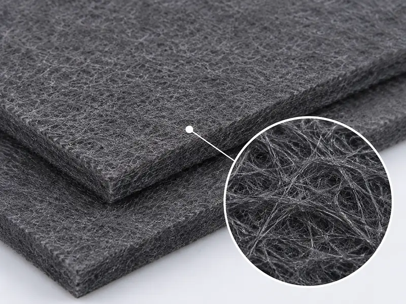
Felt Layers, Compression, and Edge Treatment
The first consideration is whether the new felt has been installed according to the original hot-zone design.
Differences in layer thickness, compression, joint arrangement, or edge treatment can affect how the insulation fits together. If the material is compressed differently from the original design, the resulting structure may not behave in exactly the same way.
It is also worth looking at how the edges and joints have been secured. Loose sections or poorly fitted interfaces may expose more fiber surface to the chamber or allow unwanted movement during operation.
These details are not necessarily the cause of slower pump-down, but they can help explain why a replacement assembly behaves differently from the previous one.
Flexible Graphite Foil and C/C Hot-Face Protection
Flexible graphite foil is often used as a protective facing over graphite felt. It helps shield the underlying insulation from direct exposure to gas flow and reduces the risk of fiber disturbance.
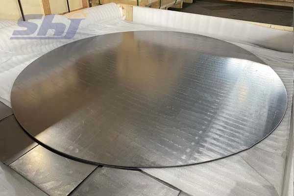
In more demanding furnace applications, C/C panels may be used to provide a stronger and more mechanically stable hot-face structure.
After replacement, the condition of the foil overlaps, panel joints, edge fixing, and fastening points should be reviewed. A change in the original overlap arrangement or the formation of enclosed spaces behind the facing may affect how gas escapes from the insulation layers.
The relationship between the facing and the felt beneath it is therefore just as important as the condition of either material individually.
A well-selected insulation material cannot compensate for an assembly that has not been restored to the intended configuration.
Possible Trapped Gas Spaces
Another aspect worth considering is whether changes to the hot-zone structure have created spaces in which gas can become temporarily trapped or released less readily.
This may occur when panel positions, foil overlaps, or supporting components are changed during installation.
Such spaces can contribute to slower evacuation, particularly when the assembly contains porous insulation and multiple layers. However, their presence and significance need to be established through inspection rather than assumed from the pump-down curve alone.
If the inspection also reveals visible damage, delamination, or changes to the structural condition of the hot zone, a broader review may be necessary. Our guide to Vacuum Furnace Hot-Zone Failure Analysis covers related structural and material considerations.
5. Which Vacuum Tests Can Help Identify the Cause?
In some cases, comparing pump-down curves and inspecting the hot zone will not provide enough information to identify the source of the additional gas load.
Further testing may then be useful. The choice of method depends on the furnace design, the suspected problem, and the diagnostic equipment available.
Pressure-Rise Testing
A pressure-rise test is commonly used to observe how chamber pressure changes after the chamber has been isolated from the pumping system.
The result can provide useful information about the gas entering or being released into the chamber during the test period.
However, pressure rise should not automatically be interpreted as evidence of an external leak. Gas released from internal surfaces, insulation materials, and other components can also contribute to the pressure increase.
Important: A pressure-rise result alone cannot distinguish an external leak from gas released inside the chamber. Interpret it alongside the isolation procedure, leak testing and other available evidence.
For that reason, the test needs to be considered alongside the chamber condition, isolation procedure, observation period, and other available measurements. Leybold explains the distinction and limitations in its technical note on pressure-rise and pressure-drop tests.
Leak Detection
Where the maintenance history or initial inspection suggests a possible leak, an appropriate leak-detection procedure can help investigate the vacuum boundary.
This is particularly relevant when the furnace door, flanges, valves, or other vacuum connections have been disturbed.
Leak detection and pressure-rise testing provide different types of information. Using them appropriately can help distinguish a problem with the vacuum boundary from additional gas release within the chamber.
Residual Gas Analysis (RGA)
Residual Gas Analysis (RGA) provides information about the composition of gases present in a vacuum chamber.
This can be useful when the pump-down behavior suggests that additional gas release or contamination may be involved. However, interpreting the results requires more than identifying an individual peak.
Different sources can contribute to similar gas signals, and the background condition of the furnace, previous processing history, cleaning procedure, and test temperature all matter.
For example, a detected gas component should not be treated as direct proof that the graphite felt is defective. RGA is most useful when its results are compared with the normal background and supported by other inspection or testing evidence.
6. Restore the Hot Zone Before Deciding on Another Replacement
Once the possible causes have been investigated, the next step is to decide whether the furnace needs system maintenance, cleaning, drying, or vacuum conditioning.
01Check the vacuum system
02Review moisture and contamination
03Inspect the hot-zone assembly
04Condition and retest where appropriate
If moisture or removable contamination is suspected, an appropriate conditioning procedure may help reduce the additional gas load. Depending on the furnace and material configuration, this may involve cleaning or a controlled vacuum bake-out.
The procedure must be suitable for the installed materials and carried out according to the furnace manufacturer's operating and safety requirements. There is no universal bake-out temperature or treatment time that can be applied to every graphite felt grade and hot-zone design.
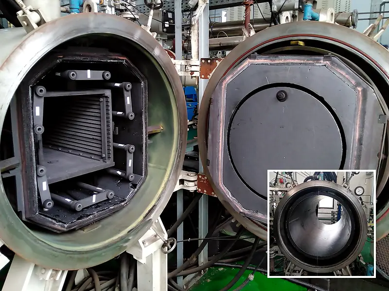
After the treatment, the pump-down test should be repeated under conditions that are as close as reasonably possible to the original comparison.
Recording the pressure-time curve, pump and valve sequence, gauge position, and relevant operating conditions makes it easier to determine whether the furnace has returned to its previous performance.
If the difference remains, further investigation may be necessary. Only when the available evidence points to the material condition or insulation configuration should another material replacement or specification change be considered.
This approach helps avoid treating every slow pump-down as a material problem when the actual cause may lie elsewhere in the system.
7. Information That Helps with a Technical Review
When the cause remains unclear, the quality of the available information can make a significant difference to the next decision.
For a technical discussion about graphite insulation or hot-zone components, it is helpful to prepare the furnace details, operating records, and information about the replacement material.
|
Information to Prepare |
Why It Matters |
|
Furnace manufacturer and model |
Establishes the equipment type and general configuration |
|
Hot-zone dimensions and layout |
Helps understand the insulation arrangement |
|
Before-and-after pump-down curves |
Shows how and when the vacuum performance changed |
|
Pump and valve sequence |
Provides context for comparing evacuation conditions |
|
Vacuum gauge type and location |
Helps assess whether the measurements are comparable |
|
Operating temperature and atmosphere |
Defines the actual application conditions |
|
Graphite felt grade, thickness, and density |
Provides a basis for reviewing the insulation specification |
|
Material storage and installation details |
Helps assess possible moisture and handling effects |
|
Photos of felt layers and hot-face panels |
Shows the installation arrangement and visible condition |
|
Leak-test, pressure-rise, or RGA reports |
Adds diagnostic information where available |
Not every furnace operator will have all of these records. Nevertheless, a clear description of the maintenance work, together with the available pump-down curves and installation photographs, can provide a useful starting point for a technical review.
8. Frequently Asked Questions
Does slow pump-down mean the new graphite felt is defective?
No. A slower pump-down after replacement does not, by itself, indicate a material defect. Changes to seals, pumping performance, measurement conditions, moisture, contamination, and hot-zone installation can also influence evacuation time. The vacuum system and assembly should be reviewed before the material is judged.
Can graphite felt affect vacuum furnace pump-down time?
Yes. Graphite felt has a porous fiber structure and a relatively large surface area, so it can retain moisture and gases after exposure to air. Its contribution to the overall gas load depends on material condition, storage, contamination, processing, and furnace conditioning.
Can a pressure-rise test distinguish a leak from outgassing?
A pressure-rise test can provide useful information, but it may not distinguish the two causes on its own. Leakage and outgassing can occur at the same time. The results should be interpreted alongside leak testing, operating records, and other available evidence.
Should I replace the graphite felt again if pump-down is slow?
Not immediately. First establish whether the pumping system, vacuum connections, measurement conditions, and hot-zone installation are contributing to the problem. Another material replacement should only be considered when the inspection and test results provide a reasonable basis for reviewing the existing felt specification.
Conclusion
When a vacuum furnace takes longer to pump down after graphite felt replacement, the first question should not be whether the new material is defective. It should be what has changed since the previous operating cycle.
The difference may be related to moisture or contamination, but it may also come from a disturbed vacuum connection, changes in pumping performance, or differences in the hot-zone assembly. Comparing pump-down records and checking these factors in a logical order provides a much better basis for identifying the problem.
For furnace operators, this distinction matters. Replacing the insulation again without understanding the cause may simply repeat the same maintenance work without resolving the underlying issue.
A more reliable approach is to establish the source of the change first, verify the result after any corrective work, and then decide whether the graphite felt material or hot-zone configuration needs to be reviewed.
Reviewing Your Graphite Insulation or Hot-Zone Configuration?
If the vacuum system and installation have been checked but pump-down performance remains different, the graphite insulation specification and hot-zone arrangement may need further review.
SHJ CARBON works with graphite and carbon-based materials, including soft and rigid graphite felt, flexible graphite components, and C/C hot-zone parts for high-temperature applications.
For a more relevant technical discussion, share your furnace model, operating conditions, available pump-down records, graphite felt specifications, and photographs of the installed hot zone.
Contact SHJ CARBON to discuss your graphite insulation and vacuum furnace hot-zone requirements.